Todos los mensajes

maffysdad 08/02/2019
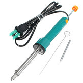
I wasn't expecting much considering how little I paid for it, but again Banggood have surprised me! So I paid about £8 UK, inc P&P etc, it arrived surprisingly quickly, attached with a two prong unfused plug and a unfused UK adaptor, but I plug these things into a short lead fused extension then into a RCD adaptor, so I at least have the minimum protection just in case. I've use d it a few times now, it's sold as a 36W 220V device and mine draws 34W, so I'm happy with that, They do state the voltage is +/- 15% which at 240V is within it's tolerance range. The hollow tip takes about 4mins to warm up to a temperature where it can melt lead based solder, push the solder sucker plunger down, apply the tip to the joint, wiggle it a little, press the release button and slurp, the solder's gone! If you don't succeed on the first attempt, such as if your doing a multilayer motherboard (where all the layers act as a heatsink), a item that's been produced in a solderbath, or one whos solder is lead free, then consider applying some lead based solder first, that works a treat. I could never afford (or justify) an expensive vacuum pumped desolder station, as much as I would love one, so this is the poor mans version, but it's working a treat and has allowed me to make a very tidy job of removing capacitors from around a CPU and remove some IC's in a fraction of the time it takes with a normal solder sucker since the heat at the tip is there all the time. It feels comfy to hold and to operate, I place my pinkie under tha cable and the rest of my hand above so that my thumb operates the plunger and button. It has a good stroke to suck the solder in, and is well sealed so you get good pressure, and with the button placed at the top means you get less of a 'kick' at the tip. The one downside so far is that it gets quite warm at the body where the heating element meets the body, and at 36W it is quite toasty, so it will be interesting to see if this heat causes any fractures or deteriorates the plastic. The instructions are on the packaging, and are in Chinese, but no matter. to empty the pump, turn it off, allow it to cool, then twist the top where the button is, anticlockwise about 30 degrees, then left apart. It is a neat little device :D I hope you find this review helpful, if you have any questions that I can answer, do get in touch and I'll try to answer them for you.
3
Recomendaciones
Comentarios (0)

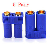
maffysdad Judging from picture 3, these are the old connectors that have the smaller contact point when joined together. Far better to go for the newer version with the over-spring on the female which offers better contact area and a more positive connection.

2019-01-31 12:01:14 Servicial (0)
Enviar
respuestas (2)

Q: how to install that tracker

Preguntado por Ansari sobre 2018-03-04 03:47:52

maffysdad Red wire goes to constant +12v battery positive. Black wire goes to constant battery negative. (The above two are your main power and keep the device battery charged. I'd red or black are cut the device can be set to warn you of power cut). Orange (optional) goes to ignition ACC or AUX. This wire just allows you to determine if the ignition has been turned on. Yellow is used to provide a +12v output to the coil of an external relay, that in turn can be placed in-line to cut power to the fuel pump. Make sure you set up the SIM card first. These are neat little trackers.

2019-01-26 03:34:11 Servicial (0)
Enviar
respuestas (1)
maffysdad 17/02/2018
I've waited to leave this review until I was sure it worked even after the trial expired, which it does, the only difference is that after the trial expires there is no Cloud storage, that is the only difference, I didn't enter any payment details and no payments have been taken, and since the trial ended I only had three emails in the first three days following it's expiry, none in the last week, so it's not annoying. You can still work, view and operate the camera and if you have a SDCard installed in the camera you can view these through the app (or by removing the SDCard from the device), all images match the quality of what you see in the app. The app works well, there is a second or two delay which is expected. Motion wise there is some 'looseness', so it may not always find the same saved location twice in a row, but it ends up close enough and there is a 'reset' function which does a full pan/tilt recall. Overall, the functions are basic but suitable for pan/tilt, playback, record, two way talking etc. Video quality is very good on normal quality and excellent on HD with realistic colour and very little edge distortion for the lens used. Sound is good, night vision is also impressive, and it's very quiet in operation when in motion. I'm pleased I took a chance with this product, it was worth the money for what I need. Angle of vision is about almost 355 degree pan, but only about 55 degrees tilt, otherwise, yeah, it's a great product when placed correctly. Do NOT be fooled by the picture which shows 90 degrees tilt, this is INCORRECT, it is only 55 degrees tilt.
0
Recomendaciones
Comentarios (1)
maffysdad 17/02/2018
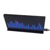
When I was younger my first stereo system had a single LED for the 'peak' record level and two needle vU meters for the stereo output, and only base, treble and tone. My next stereo had lost the needles and instead had 5 LED's per channel which acted for both the vU output and the record level, again, only base, treble and tone. My best stereo had a five band graphic equaliser and a five band line bar spectrum analyser. Sadly this stereo went bang! :'-( My current stereo has a single needle vU output, I modded it a stereo vU 10 LED output, but home stereo's have gone out of fashion, these days everything is mobile and power saving, so LED's are a no, no or they're hidden in menu's or worse, are called 'Visualisations' which is just psychedelic and doesn't offer much. I'm very much into my LED's, stage lights, dot matrix and such, and so when I saw this on the web I just had to have it! Well, a few minutes of soldering discrete components, followed by a few hours of soldering blue and red LED's, (336 LED's or 672 LED solder joints to be exact), powered up, (found instructions on how to change from LINE IN to MIC IN as the ones on the sheet are not in English), but then WOOHOO!!!! Back to dancing LED's!!!... I am seriously loving it!... It's a spectrum/frequency analyzer first and foremost that per frequency had a vU level. If you watch the video on the page where the item is for sale you see the guy test it with a frequency generator, It's actually spot on and doesn't need any tuning. There are two resistor pot's that are used to adjust AGC and something else, It came with two chips and one DIL resistor package pre-soldered (thankfully as they were super fine), but there is plenty left to solder. several chips, a few voltage regulators, a dozen capacitors, some resistors, and all those LED's! Would I buy another? Yeah!... I loved building it and it's adorable to watch and remember the good old days, plus the case fits a treat and it is wonderful to just watch!... I wonder if BangGood would send me another for free? I do hope so!... :-D
0
Recomendaciones
Comentarios (0)
maffysdad 07/01/2018
I was pleased to receive this product, I love anything LED, and bar graphs I find amazing. I purchased the DIY build but there is also a pre-built version on BG, but I do enjoy the building. The build and mode instructions were in fairly good English, and fairly informative on identification of component orientation and the PCB is silkscreened quite well also. I mostly used solder paste for this build at a temp of 330degC, but even the SMD IC would be possible with a fine tip soldering iron and SWG26 solder. I soldered the resistors, then checked the resistance value of each one before moving on. Next the transistors, followed by the IC, this was the first significant SMD IC with lots of pins I'd done, (phew, nice and easy!), next was the capacitor, button & USB connection. I then built the case with the paper protection still on so I could check the height of the DIL bar graph LED's and discovered the DIL LED body sat flush to the PCB, I used a diode checker to double check the orientation of these components, then place them through the board and on a flat surface, solder just the four edge pins of each DIL LED, checked the alignment of each bar graph and adjusted where needed, once happy soldered all the legs, and once soldered in don't cut those legs/pins, they hold the PCB at the correct height to the case. At this point you can test the build, mine worked first time :-D Remove the paper from the plastic case parts by soaking in warm water and a touch of hand soap for 10minures, dry, then build the case, back, sides, top, bottom, leaving off the front for now. Insert the PCB build, then add the front. Now power up and using the supplied double adaptor 3.5mm connector use headphones to listen to your music and watch the display. Brilliant! Wish I could afford the really huge display BG do, I'd be in heaven! :-D
0
Recomendaciones
Comentarios (0)